
Rebar Sizes Chart
A rebar sizes chart with ASTM A615 diameters, weight per foot, and cross-sectional area for #3 to #18 bars, plus how to read and apply each size.
Pull a length of reinforcing bar off the rack at any builders' merchant and you will find a number rolled into the steel every few inches — a 4, a 5, sometimes a 6. That number is the entire language of rebar. This rebar sizes chart sets out what each designation means: the diameter, the weight, and the steel area behind every bar number from #3 through #18, so you can match the bar in your hand to the one called out on the drawing.
Every figure below follows ASTM A615/A615M, the standard specification for deformed carbon-steel reinforcing bars used across the United States. The values are fixed by the standard — a #5 bar is the same diameter and weight whether it comes from a mill in Ohio or a stockholder in Texas. That consistency is what lets an engineer specify "#5 at 12 inches on centre" and trust that the steel delivered to site matches the structural calculation.
The ASTM A615 Rebar Size Chart
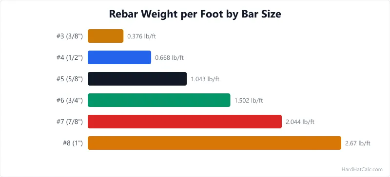
The table covers the eleven imperial (inch-pound) bar sizes in the standard, alongside their soft-metric designations. Diameter, cross-sectional area, and unit weight are the three numbers you reach for most: diameter for fit and cover, area for how much steel resists tension, and weight for ordering and pricing.
| Bar Size | Soft-Metric | Diameter (in) | Diameter (mm) | Area (in²) | Weight (lb/ft) | Mass (kg/m) |
|---|---|---|---|---|---|---|
| #3 | #10 | 0.375 | 9.5 | 0.11 | 0.376 | 0.560 |
| #4 | #13 | 0.500 | 12.7 | 0.20 | 0.668 | 0.994 |
| #5 | #16 | 0.625 | 15.9 | 0.31 | 1.043 | 1.552 |
| #6 | #19 | 0.750 | 19.1 | 0.44 | 1.502 | 2.235 |
| #7 | #22 | 0.875 | 22.2 | 0.60 | 2.044 | 3.042 |
| #8 | #25 | 1.000 | 25.4 | 0.79 | 2.670 | 3.973 |
| #9 | #29 | 1.128 | 28.7 | 1.00 | 3.400 | 5.060 |
| #10 | #32 | 1.270 | 32.3 | 1.27 | 4.303 | 6.404 |
| #11 | #36 | 1.410 | 35.8 | 1.56 | 5.313 | 7.907 |
| #14 | #43 | 1.693 | 43.0 | 2.25 | 7.650 | 11.380 |
| #18 | #57 | 2.257 | 57.3 | 4.00 | 13.600 | 20.240 |
Notice the gap in the numbering: the imperial set jumps from #11 to #14, then to #18, with no #12, #13, #15, #16, or #17. Those three large bars (#14 and #18) descend from old square-bar stock — the #14 matches the cross-section of a 1.5-inch square bar, and the #18 matches a 2-inch square — so they slot in where their area lands, not where the next sequential number would fall. The #14 and #18 are mill-order items used in heavy columns, bridge piers, and foundation mats; you will almost never see them on a house.
What the Bar Number Actually Tells You
For the small bars, the system is elegant: the bar number is the diameter measured in eighths of an inch. A #3 bar is 3/8 inch across, a #4 is 4/8 (half an inch), a #5 is 5/8, and so on up to the #8, which is exactly 1 inch. Divide the bar number by 8 and you have the nominal diameter in inches. This rule holds cleanly from #3 to #8.
Above #8 the tidy fraction breaks down. A #9 bar is not 9/8 inch (1.125 would be close, but the listed diameter is 1.128); #10 and #11 likewise carry diameters that come from matching the area of the old 1-inch, 1-1/8-inch, and 1-1/4-inch square bars rather than a simple eighths rule. So the eighths shortcut is a reliable mental check for #3 through #8 and an approximation beyond that.
There is a second shortcut worth memorising for ordering. The weight of a bar in pounds per foot is roughly the bar number squared, divided by 24. A #5 bar: 5 × 5 = 25, divided by 24, gives 1.04 lb/ft — which matches the chart's 1.043 almost exactly. A #8: 64 ÷ 24 = 2.67 lb/ft, again spot on. The formula works because steel weighs about 490 pounds per cubic foot, and the maths of a round cross-section collapses neatly into that divisor. When you need to weigh a steel order in your head on site, that is the trick.
- Diameter: bar number ÷ 8 (exact for #3–#8)
- Weight: bar number² ÷ 24 (good to within 1% across the range)
- Area: read from the chart — it drives the structural design, so do not approximate it
Which Rebar Size Goes Where
Bar selection follows the load. Light, crack-control reinforcement uses small bars; heavily loaded structural members use big ones. Here is where each common size earns its place on residential and light-commercial work.
#3 and #4 handle the bulk of homeowner concrete. A #3 (3/8 inch) ties stirrups and column hoops and reinforces thin slabs and small pads. A #4 (1/2 inch) is the workhorse for slabs on grade, driveways, patios, and footings on ordinary residential soils. If you are reinforcing a garage slab, #4 at 16 inches on centre each way is a typical call. The amount of steel a slab or footing needs comes straight out of a grid layout for slab and footing steel, which converts spacing into bar count and total weight.
#5 and #6 step up to foundation walls, grade beams, and the footings under two-storey loads. A #5 (5/8 inch) is the most common vertical-and-horizontal bar in a poured foundation wall; a #6 (3/4 inch) appears where spans grow or soil bearing is poor. Sizing the footing itself — width, depth, and the concrete volume that drives your bar layout — is the job of a continuous footing sizing tool. For isolated pads under deck posts and porch columns, a pier and pad footing sizer sets the dimensions you then reinforce.
#7 through #11 belong to engineered work: heavily loaded columns, transfer beams, retaining walls holding back serious height, and commercial foundations. Once you are specifying #8 and above, the design is almost always coming from a stamped drawing rather than a rule of thumb. #14 and #18 are the giants — reserved for bridge substructures, high-rise columns, and mat foundations, ordered direct from the mill.
From the Chart to a Lap Splice
Reinforcing bar comes in stock lengths — commonly 20, 30, 40, or 60 feet. Any run longer than the stock length, or any joint where two pours meet, needs the bars to overlap so force transfers from one bar into the next. That overlap is a lap splice, and its length scales directly with the bar diameter you just read off the chart: bigger bar, longer splice.
The relationship is not linear, because concrete strength, bar coating, and how many bars splice at one location all feed into it. The tool below works the overlap out per ACI 318 once you pick the bar size and conditions. Try it with a #5 in 4,000 PSI concrete to see a typical foundation-wall splice.
Bar number equals eighths of an inch in diameter. #5 = 5/8" diameter.
Compressive strength of concrete. 3,000 PSI is residential minimum; 4,000 PSI is standard for foundations.
Epoxy-coated bars need longer splices because the coating reduces bond with concrete.
Class B applies when more than half the bars are spliced at the same cross-section. Most field splices are Class B.
Standard means cover is at least one bar diameter and clear spacing between bars is at least twice the diameter.
For estimation only. Structural work requires review by a licensed engineer. Local building codes take precedence over any calculator output.
How This Is Calculated
Development length ld = (fy × ψt × ψe) / (D × λ × √f'c) × db × confinement factor, where D is the ACI simplified-method size-class divisor: 25 for bars #6 and smaller, 20 for #7 and larger (the bar-size effect lives in the divisor — no separate ψs). Lap splice length = ld × splice class multiplier (Class A: 1.0, Class B: 1.3), rounded up to the nearest inch. fy = 60,000 PSI (Grade 60 rebar). ψt = 1.0 (bottom bars), ψe = 1.0 (uncoated) or 1.5 (epoxy, conservative), λ = 1.0 (normal-weight concrete). Confinement factor 1.5 for tight cover/spacing. Bar diameters per ASTM A615 (#9 = 1.128 in, #10 = 1.270 in). Minimum development length and lap splice: 12 inches.
Source: Development length per ACI 318-19 Table 25.4.2.3 (simplified method: divisor 25 for #6 and smaller, 20 for #7 and larger). Lap splice classes per ACI 318-19 Table 25.5.2.1. Bar diameters per ASTM A615/A615M. Output values reconciled July 2026 against the ATC/SEAOC Class B lap splice design aid (Grade 60, normal-weight, uncoated bottom bars). Re-checked September 2026 against three free published tables: Dayton Superior Rebar Splicing Handbook Table 1.11 prints the same eight Class B lap lengths at 3,000 and 4,000 PSI for uncoated bottom bars, and both the WSDOT Bridge Design Manual Appendix 5.1-A7 and TxDOT Standard Specification Item 440 Table 6 apply the same 1.5 multiplier to epoxy-coated bars.
If you want the underlying method rather than just the number, the full overlap length method for spliced bars walks through the development-length formula and the Class A versus Class B distinction. One point that trips people up: the splice length depends on the square root of the concrete's compressive strength, so a stronger mix shortens the splice. How that strength is set by the cement, sand, and aggregate proportions is covered in the breakdown of how mix proportions set compressive strength — worth reading before you assume a richer mix and a smaller bar will save steel.
Imperial Bars vs Soft-Metric Designations
The soft-metric column in the chart is not a different bar — it is the same physical steel relabelled. In the late 1990s the US reinforcing-steel industry adopted metric designations to align with international practice, but mills kept rolling the existing inch-pound diameters. So a soft-metric #16 bar is identical to the imperial #5: 0.625 inch, 15.9 mm, the same 200 mm² of steel. The metric number is the diameter in millimetres rounded to a whole figure, which is why #16 (15.9 mm) and #19 (19.1 mm) look like near-misses rather than round numbers.
This matters in two situations. First, when you read older drawings or imported product literature that lists bars in metric — you need to know that #16 means a half-inch-plus bar, not something new. Second, when you work in millimetres for cover and spacing but order bar by imperial number. The chart gives you both columns side by side so you never have to convert under pressure. True hard-metric bars (genuinely different diameters like 10, 12, 16, 20, 25 mm) exist in Europe and elsewhere, but they are a separate system from the soft-metric relabelling used in North America.
Common Mistakes When Reading a Rebar Chart
Confusing diameter with area. Doubling the bar diameter does not double the steel. Area grows with the square of diameter, so a #8 (1 inch, 0.79 in²) carries nearly four times the steel of a #4 (0.5 inch, 0.20 in²), not twice. When a drawing changes a bar size, check the area column, not the diameter — that is what the structural design actually depends on.
Assuming the eighths rule holds for big bars. It does not past #8. A #11 is not 11/8 (1.375) inch; it is 1.410 inch. For #9, #10, #11, #14, and #18, read the diameter from the chart rather than dividing by eight, or your cover and spacing maths will drift.
Ignoring weight when pricing. Rebar is sold by weight, not by length. Two jobs needing the same total footage of #4 and #6 bar will price very differently, because the #6 weighs more than double the #4 per foot (1.502 versus 0.668 lb/ft). Use the weight column to turn a bar schedule into a tonnage figure before you ask for a quote.
Forgetting the splice and waste allowance. The chart tells you what a bar weighs, but it does not tell you how much extra you need for overlaps. Every lap splice adds bar that carries no net length, and offcuts add more. On a long foundation wall, splice overlaps alone can add 8–12% to the steel weight. Size the splices first, then order.
Keep the chart within reach during layout and ordering. Match the bar in your hand to the number on the plan, read the area when the design changes, weigh the order from the lb/ft column, and let the splice length follow from the diameter. That sequence turns a rolled-in number into a steel order you can trust.
Frequently Asked Questions
- What size is #4 rebar?
#4 rebar is 1/2 inch (0.500 in, or 12.7 mm) in nominal diameter, with a cross-sectional area of 0.20 square inches and a weight of 0.668 pounds per foot. Its soft-metric designation is #13. The bar number tells you the diameter directly: a #4 is four-eighths of an inch, which reduces to one half. It is the most widely used bar in residential work, common in slabs on grade, driveways, patios, and standard footings. To turn a #4 layout into a total bar count and weight, a slab and footing steel layout tool converts spacing into quantities for your pour.
- How do you calculate rebar weight per foot?
The quickest field method is to square the bar number and divide by 24. For a #5 bar that is 25 ÷ 24 = 1.04 pounds per foot, which matches the ASTM A615 listed weight of 1.043 lb/ft almost exactly. The formula works because reinforcing steel weighs about 490 pounds per cubic foot, and that density combined with a round cross-section collapses into the divisor of 24. For an exact figure, read the weight column straight from the chart above rather than rounding. When you are pricing concrete and steel together, the concrete cure schedule planner helps you plan the pour timeline that your reinforcement sits inside.
- What is the difference between imperial and soft-metric rebar sizes?
They label the same physical bars. A soft-metric #16 bar is identical to an imperial #5 — same 0.625-inch diameter, same 200 mm² of steel — because US mills adopted metric designations in the late 1990s without changing the actual bar diameters. The soft-metric number is simply the diameter in millimetres rounded to a whole value, which is why it reads as 16 rather than a clean round figure. This differs from true hard-metric bars used in Europe, which have genuinely different diameters (10, 12, 16, 20 mm). If a drawing lists bars in metric, the soft-metric column in this chart maps each one back to its familiar imperial number.
- How do you use a rebar chart to size a lap splice?
Start by reading the bar diameter from the chart, because lap splice length scales with diameter — a larger bar needs a longer overlap. The chart alone does not give the splice length, though: that also depends on the concrete strength, whether the bar is epoxy-coated, and how many bars splice at the same location (Class A versus Class B). A #5 bar in 4,000 PSI concrete needs roughly a 31-inch Class B splice, while a #4 in the same conditions needs about 25 inches. Use the bar overlap length method to work the exact overlap for your bar size and conditions before cutting steel.