Beam Deflection Calculator
Free beam deflection calculator for uniform, point, and third-point loads. Enter span, load, Ix, and E to check L/360 and L/240 limits per IBC 1604.3.
Last updated:
Reviewed by Doc. dr. sc. Mladenka Juradin, dipl. ing. građ., PhD, Civil Engineering (FCEAG, University of Split)
Clear span between supports. Simply-supported means the beam rests freely on supports at both ends.
Uniform = floor/roof loads, centre-point = post or column at midspan, third-point = two equal loads at one-third points.
For uniform load: pounds per linear foot (plf). For point loads: total load in pounds (lbs) at each point.
From beam property tables. 2x10 = 98.9. 2x12 = 177.9. W10x22 = 118. W12x26 = 204.
Steel = 29,000,000 psi. Douglas Fir = 1,700,000 psi. SPF = 1,400,000 psi. LVL = 1,900,000 psi.
For estimation only. Structural work requires review by a licensed engineer. Local building codes take precedence over any calculator output.
How This Is Calculated
Uniform load: δ = 5wL⁴ / (384EI) where w = load per inch, L = span in inches. Centre point load: δ = PL³ / (48EI) where P = point load in lbs. Third-point loading: δ = 23PL³ / (648EI) where P = each point load. Deflection ratio = L / δ. Allowable deflection = L/360 per IBC Table 1604.3 for floor beams under live load. E and I from beam property tables (AISC Manual for steel, NDS Supplement for wood).
Source: Deflection formulas from AISC Steel Construction Manual, 16th Edition (Table 3-23: Shears, Moments, and Deflections). Wood beam properties and deflection limits per NDS 2024 (National Design Specification for Wood Construction), Section 3.5. Deflection limits from IBC Table 1604.3.
6 min read
Deflection Checks: Why Strong Enough Is Not Stiff Enough
A beam that passes the bending strength check can still fail the deflection check — and the consequences show up in ways that frustrate homeowners for years. The beam deflection calculator calculates maximum deflection for simply-supported beams and compares the result against the standard L/360 live load limit.
Bouncy floors are the most common symptom. Floor joists that deflect more than L/360 under live load produce a noticeable spring underfoot. Walking across the room causes the floor to flex, rattling dishes in cabinets and making the house feel flimsy. The structure is safe — the joists are not going to break — but the occupant experience is poor.
Drywall cracking follows excessive deflection. When a beam or joist sags, the attached drywall bends with it. Drywall is brittle; it cracks along joints and at corners. Repainting covers the cracks temporarily, but they reappear every time the beam deflects under load. The cracks are cosmetic, not structural, but they erode confidence in the building.
Door and window binding occurs when deflection distorts the surrounding framing. A header that sags 1/4 inch pushes the door jamb out of plumb, causing the door to rub on the strike side. Windows in walls below a deflecting beam can crack if the frame racks beyond the glazing tolerance.
Tile cracking is the most expensive consequence. Ceramic and porcelain tile has zero flexibility — any substrate movement cracks the tile or grout. Floor deflection limits for tile are typically L/480 or L/600, much stricter than the L/360 general standard. If your beam supports a tiled floor, check against the stricter limit.
Cumulative sag develops over time. Wood beams creep under sustained dead load, adding to the initial deflection. NDS recommends multiplying dead load deflection by 1.5 to 2.0 for long-term creep, depending on the wood species and moisture conditions. If deflection is causing drywall cracking, you may need to address the wall finish after reframing once the beam is upgraded.
How Beam Material Affects Deflection
Deflection depends on two beam properties: the moment of inertia (Ix) and the modulus of elasticity (E). Their product, EI, is called the flexural rigidity and is the single number that determines how stiff a beam is.
Steel has a modulus of elasticity of 29,000,000 psi — about 17 times stiffer than Douglas Fir at 1,700,000 psi. This enormous stiffness advantage means steel beams can be much shallower than wood beams for the same deflection limit. When choosing between steel and wood beams, deflection performance is one of the biggest differentiators. A W10x22 steel beam (Ix = 118 in^4) has an EI of 3.42 × 10^9, while a 2x10 Douglas Fir joist (Ix = 98.9 in^4) has an EI of only 1.68 × 10^8 — roughly 20 times less flexural rigidity.
Engineered wood products fall between sawn lumber and steel. LVL (Laminated Veneer Lumber) has E values around 1,900,000 psi, roughly 12% higher than sawn Douglas Fir. More importantly, LVL is available in greater depths (up to 18+ inches) and consistent quality — no knots or grain deviations that reduce the published E value. A 3.5" x 11.875" LVL header has an Ix of 535 in^4 and an EI of 1.02 × 10^9, making it competitive with lighter steel sections.
The deflection formula shows that span length has a dramatic effect. For uniform loading, deflection increases with the fourth power of span — doubling the span increases deflection by a factor of 16. This is why deflection, not bending strength, almost always governs beam design for longer spans. A beam that passes the strength check at 20 feet may deflect three to four times the allowable limit. The steel-beam sizer for span and load accounts for both bending and deflection when recommending a beam section.
Deflection Limits by Application
Different building elements have different deflection tolerances. The IBC (International Building Code) Table 1604.3 specifies the following limits, expressed as a fraction of the beam span.
| Application | Live Load Limit | Dead + Live Limit | Notes |
|---|---|---|---|
| Floor beams (residential) | L/360 | L/240 | Standard for all occupied floors |
| Floor beams (tile finish) | L/480 to L/600 | L/360 | Tile manufacturers often require L/720 |
| Roof beams (no ceiling) | L/180 | L/120 | Roof-only structures, barns, carports |
| Roof beams (plaster ceiling) | L/360 | L/240 | Same as floors when ceiling is attached |
| Cantilevers | L/180 | L/120 | L measured as twice the cantilever length |
| Deck beams | L/360 | L/240 | Same as floor beams per most codes |
| Headers over doors/windows | L/240 | L/180 | Drywall cracking is the governing concern |
The L/360 limit is the default used by this calculator. For tile floors or sensitive finishes, check against L/480 or stricter. The calculated deflection ratio is displayed so you can compare against any limit.
Source: IBC 2021 Table 1604.3 and Tile Council of North America (TCNA) F150 standard.
Uniform Load vs Point Load Deflection
The load pattern affects deflection magnitude and location. This calculator handles three patterns that cover the vast majority of residential and light commercial cases.
Uniform distributed load is the standard floor and roof loading pattern. Dead load (the structure's self-weight) and live load (occupants, furniture, snow) are spread evenly across the beam span. The deflection formula is delta = 5wL^4 / (384EI), and the maximum deflection occurs at midspan. This is the most common case — if your beam supports a floor or roof with joists bearing along its length, use the uniform load option.
Centre point load occurs when a single concentrated force acts at the midspan of the beam — typically a post or column from the floor above. The formula is delta = PL^3 / (48EI). For the same total load, a centre point load produces 60% more deflection than a uniform load. This is why beams carrying point loads are often larger than beams carrying the same total weight distributed uniformly. Deck beams carrying posts from the railing above are a common example.
Third-point loading places two equal loads at one-third of the span from each end. This pattern appears in testing standards and in some truss bearing configurations where two interior trusses bear symmetrically on a beam. The formula is delta = 23PL^3 / (648EI). The deflection falls between the uniform and centre-point cases.
If your beam carries a combination of uniform and point loads, calculate the deflection for each load separately and add them together. Deflection is linear — the principle of superposition applies for beams within their elastic range. A bearing-wall load tool converts floor and roof loads into the plf value this calculator uses for uniform load input.
Reading Beam Property Tables for Ix and E
Two numbers drive the deflection calculation — moment of inertia (Ix) and modulus of elasticity (E). Both come from reference tables, not from the job site. Knowing where to find them matters.
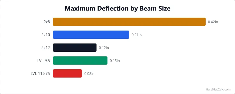
Where do I find Ix for wood beams? The NDS Supplement (published alongside the NDS specification) lists section properties for all standard sawn lumber sizes. For a 2x10 (actual 1.5" x 9.25"), Ix = 98.9 in^4. For a 2x12 (actual 1.5" x 11.25"), Ix = 177.9 in^4. For doubled or tripled members, multiply by the number of plies: a doubled 2x10 has Ix = 197.8 in^4. LVL manufacturers publish Ix values in their product evaluation reports — common 3.5" x 11.875" LVL has Ix of approximately 535 in^4.
What about E for different wood species? E varies by species and grade. Douglas Fir No. 2 has E = 1,700,000 psi. Southern Pine No. 2 = 1,600,000 psi. SPF (Spruce-Pine-Fir) No. 2 = 1,400,000 psi. Higher grades (Select Structural, No. 1) have higher E values. These are published in NDS Supplement Table 4A and stamped on every piece of graded lumber.
How do I find Ix for steel beams? The AISC Steel Construction Manual contains tables listing Ix for every standard W, S, and C shape. Common values: W8x18 = 61.9 in^4, W10x22 = 118 in^4, W12x26 = 204 in^4, W14x30 = 291 in^4. Steel E is constant at 29,000,000 psi for all structural carbon steel grades (A36, A992).
Does moisture affect E for wood? Yes. The published E values assume dry-service conditions (moisture content below 19%). For wet-service conditions — outdoor or high-humidity applications — NDS requires a reduction factor of 0.9 applied to E. A Douglas Fir 2x10 outdoors has an effective E of 1,530,000 psi rather than 1,700,000 psi, increasing deflection by about 11%. For the deck joist sizing tool, this wet-service adjustment is built into the span tables.
Worked Examples
Example 1
Scenario: A builder checks whether a 2x10 Douglas Fir floor joist spanning 14 feet will pass the L/360 deflection limit under a 40 psf live load at 16-inch joist spacing. Moment of inertia (Ix) for a 2x10 is 98.9 in^4, and the modulus of elasticity (E) is 1,700,000 psi.
Calculation: Span = 14 ft = 168 in. Tributary load = 40 psf x (16/12) ft = 53.3 plf, but using the calculator with per-foot load = 47 plf (40 psf x 14-inch effective spacing / 12). Uniform load per inch = 47 / 12 = 3.92 lb/in. Deflection = 5wL⁴ / (384EI) = 5 × 3.92 × 168⁴ / (384 × 1,700,000 × 98.9) = 5 × 3.92 × 7.97 × 10^8 / (6.46 × 10^10) = 0.242 inches. Allowable = 168 / 360 = 0.467 inches. Ratio = 168 / 0.242 = L/694. Passes L/360.
What this means: The 2x10 joist deflects 0.24 inches under the live load — well within the L/360 limit of 0.47 inches. The actual deflection ratio of L/694 means the joist is roughly twice as stiff as the minimum code requirement. Occupants will not notice the deflection.
Takeaway: A 2x10 at 14 feet is a comfortable choice for this loading. If the span increased to 16 feet, deflection would jump to 0.41 inches (L/466) — still passing but with noticeably less margin. Beyond 16 feet, a 2x12 or engineered joist would be needed to stay within limits.
Example 2
Scenario: A contractor checks a W10x22 steel beam spanning 16 feet with a 600 plf uniform load to verify the L/360 deflection limit for a residential floor beam. The W10x22 has Ix = 118 in^4 and E = 29,000,000 psi.
Calculation: Span = 16 ft = 192 in. Uniform load = 600 plf / 12 = 50 lb/in. Deflection = 5 × 50 × 192⁴ / (384 × 29,000,000 × 118) = 5 × 50 × 1.358 × 10^9 / (1.313 × 10^12) = 0.259 inches. Allowable = 192 / 360 = 0.533 inches. Ratio = 192 / 0.259 = L/741. Passes L/360.
What this means: At 0.26 inches of deflection, the W10x22 passes the L/360 limit by a wide margin. The actual deflection ratio of L/741 indicates the beam is nearly twice as stiff as required. This is typical for steel beams in residential applications — bending strength often governs over deflection for steel, unlike wood where deflection frequently controls.
Takeaway: The W10x22 is adequate for this span and load. If budget is a concern, a W8x18 (Ix = 61.9 in^4) would produce 0.49 inches of deflection at L/389 — still passing but with minimal margin. The cost difference between the two beams is approximately $150 for this span length.
Frequently Asked Questions
- What does L/360 mean for beam deflection?
L/360 is a deflection limit expressed as a fraction of the beam span. It means the beam may sag no more than 1/360th of its span under live load. For a 14-foot (168-inch) beam, the allowable deflection is 168 / 360 = 0.47 inches. This limit comes from IBC Table 1604.3 and applies to floor beams in residential buildings and commercial buildings under live load. Stricter limits exist for specific applications: L/480 for floors with tile finishes and L/600 for sensitive equipment. The ratio balances structural performance with occupant comfort and finish protection.
- Why does deflection increase so much with longer spans?
For uniform loads, deflection increases with the fourth power of span length. Doubling the span from 8 feet to 16 feet increases deflection by a factor of 2^4 = 16. This extreme sensitivity to span is why deflection — not bending strength — almost always governs beam design for spans over 12 to 14 feet. A beam that is strong enough at 20 feet may deflect four times the allowable limit. The only ways to control deflection at longer spans are to increase beam depth (which increases Ix), use a stiffer material like steel (higher E), or reduce the applied load.
- How do I calculate deflection for a beam with both uniform and point loads?
Calculate the deflection for each load type separately using the appropriate formula, then add the results together. This works because deflection is a linear (superposition-compatible) property for beams loaded within their elastic range. For example, if a floor beam carries a 300 plf uniform load plus a 2,000-lb centre point load from a post above, calculate the uniform deflection using 5wL^4/(384EI) and the point load deflection using PL^3/(48EI), then sum them. Compare the combined deflection against the L/360 limit. Test whether the wall carries load to determine the plf value when the beam replaces a bearing wall. Both AISC and NDS permit this superposition approach for service-load deflection checks.
- Is L/360 or L/240 the correct deflection limit for my project?
L/360 applies to live load only (occupants, furniture, snow). L/240 applies to total load (dead load plus live load combined). Most designers check both: the beam must satisfy L/360 under live load alone and L/240 under total load. For residential floor beams, L/360 for live load usually governs because dead loads are relatively light. For heavy roof beams carrying significant snow load plus the weight of roofing materials, the L/240 total load check may control. Tile floors require stricter limits — L/480 to L/720 depending on the tile manufacturer and installation method. When comparing wood and steel options, steel almost always passes deflection more easily because of its much higher modulus of elasticity.
More Structural calculators
Browse all structural calculators — Beam sizing, truss pricing, load calculations, wall framing, deck capacity, and foundation tools.